
Having a clear and accurate John Deere ignition switch wiring diagram can save you time, prevent costly mistakes and ensure your John Deere machinery runs smoothly. In this guide, we’ll cover everything you need to know about the ignition switch wiring diagram, common wiring setups, and practical tips to help you navigate these electrical systems with confidence.
What Is An Ignition Switch for John Deere Equipment?
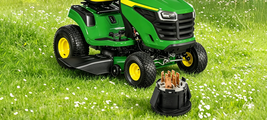
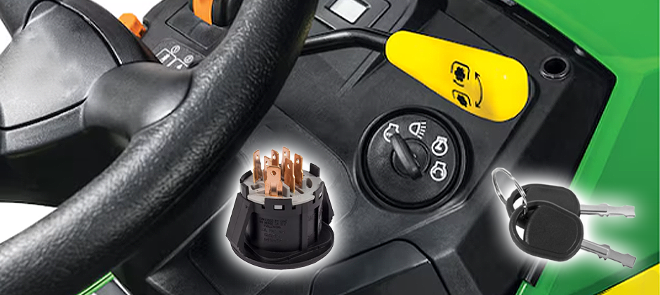
Before diving into John Deere ignition switch diagrams, it’s important to know the basics of these ignition switches. The ignition switch is a crucial device that delivers electrical power from the battery to the starter motor and ignition coil, bringing your engine to life and powering other essential components in your John Deere machinery. Once it fails, you may run into bad ignition switch symptoms, such as starting problems. Understanding how your ignition switch is wired can help you diagnose these issues effectively.
How to Read An Ignition Switch Diagram for John Deere?
Now, let’s get down to the John Deere ignition switch wiring diagram. The wiring diagrams may vary slightly depending on the model and year of your equipment. However, several common features remain consistent across many machines.
Typical Components in the Ignition Switch Circuit
The wiring diagram for a John Deere ignition switch often includes several key components:
- Battery: Supplies the electrical power
- Ignition Switch: Controls power flow to the starter and ignition system
- Starter Solenoid: Acts as a relay to engage the starter motor
- Starter Motor: Turns the engine over to start it
- Ignition Coil: Provides the spark for combustion
- Fuse or Circuit Breaker: Protects the circuit from electrical surges
- Having a wiring diagram helps you see how these elements connect, making troubleshooting far more straightforward.
Ignition Switch Terminal Identification
An ignition switch usually includes five terminals:
- Battery(B): This is the main battery positive input terminal and serves as the primary power feed and remains hot at all times, regardless of key position.
- Starter Solenoid(S): This terminal connects to the starter solenoid. It is only energized momentarily when the key is turned to the START position and automatically opens once the key is released.
- Magneto(M): This terminal connects to the ignition coil or magneto. It operates on reverse logic compared to the other terminals. It remains open during normal engine operation and is pulled to ground when the key is turned to the OFF position, which shorts out the magneto and shuts the engine down.
- Accessory(A): This terminal powers the accessory circuit. It becomes hot when the key is turned to the ACC position, supplying power to accessories such as the radio and instrument panel.
- Run/Regulator(R): This terminal connects to the voltage regulator and ignition system. It is energized when the key is in the RUN position and serves as the primary power supply for engine operation.
The following table provides a quick reference for the status of each terminal at every key position.
| Key Position | B | A | R | S | M |
|---|---|---|---|---|---|
| OFF | Hot | Open | Open | Open | Grounded |
| ACC | Hot | Hot | Open | Open | Open |
| RUN | Hot | Hot | Hot | Open | Open |
| START | Hot | Open | Hot | Hot | Open |
*Notes on terminology
Hot means the terminal is energized/has battery voltage present;
Open means the terminal is disconnected/no power;
Grounded specifically for the M terminal means it is pulled to ground, which kills the magneto/ign;
Some technical manuals may also use “Energized” instead of Hot, and “De-energized” instead of Open;
“Hot” and “Open” tend to be more common in workshop and service manual language.
John Deere Ignition Switch Wiring Color Code
The wiring diagram for the John Deere ignition switch uses color-coded wires, including:
- Red: Typically the main power wire from the battery to the ignition switch
- Yellow: Often used to connect the ignition switch to the starter solenoid
- Black or Black/White: Ground wires or ignition coil connections
- Green: May be used for accessory circuits or safety switches
Knowing what these colors represent can speed up your repair work and minimize the risk of incorrect connections.
Typical Wiring Path in the Diagram
In a standard John Deere ignition switch wiring diagram, power flows as follows:
- The battery sends power through a red wire to the ignition switch.
- When the key is turned to the “start” position, the ignition switch sends current via a yellow wire to the starter solenoid.
- The solenoid activates the starter motor, cranking the engine.
- Simultaneously, the ignition switch powers the ignition coil, producing the spark necessary for combustion.
- Once the engine starts, releasing the key to the “run” position maintains power to the ignition coil and other essential systems.
This simple sequence is the foundation of most John Deere ignition systems.
How to Use A John Deere Ignition Switch Diagram Efficiently?
Having the ignition switch wiring diagram at hand can be a lifesaver when diagnosing electrical issues. Here are the steps for interpreting the wiring diagrams.
- Identify Your Model and Wiring Diagram Version: Locate the correct wiring diagram for your specific John Deere model and year. Using the wrong diagram can lead to miswiring and further damage.
- Gather Necessary Tools: Before starting, make sure you have the following on hand: a multimeter or test light, wire strippers and crimpers, electrical tape and heat shrink tubing, and screwdrivers and pliers.
- Trace the Wiring Step by Step: Follow each wire from the battery to the ignition switch, then from the switch to each connected component. Test continuity and voltage at every segment to pinpoint the fault.
- Replace or Repair Faulty Components: Once the issue is identified, use the diagram to guide replacement of wires, connectors, or the ignition switch itself. Always opt for OEM or high-quality aftermarket parts to ensure long-term reliability.
Troubleshooting Common Issues with the Diagram
The following table lists common problems, causes and how the ignition switch wiring diagram can help to address them efficiently.
| Symptoms | Possible Causes | How the Diagram Helps |
|---|---|---|
| Engine won’t start | Broken wire, faulty ignition switch, or dead solenoid | Trace voltage flow from battery → ignition switch → starter solenoid using a multimeter(See full guide on How to Test A Starter Solenoid?) |
| Starter motor doesn’t engage | Damaged yellow wire or connector between ignition switch and solenoid | Locate the S terminal connection and test continuity along the yellow wire |
| Intermittent power loss | Loose or corroded connections in the ignition circuit | Identify ground wires and fuse connections to inspect and clean |
Practical Tips for Maintaining Your John Deere Ignition System
Prevention is a wiser solution. Doing regular maintenance can prevent many ignition switch wiring problems.
- Keep Connections Clean: Dirt and corrosion impact electrical flow. Regularly clean battery terminals and switch connectors.
- Inspect Wiring Insulation: Check for cracks or wear that could cause shorts or open circuits.
- Use Dielectric Grease: Applying this grease on connectors can protect against moisture and corrosion.
- Secure Wiring Harnesses: Prevent wires from rubbing against sharp edges or moving parts.
These simple steps can help extend the life of your ignition system and reduce downtime.
Final Words
Understanding the John Deere ignition switch diagram is essential to your electrical systems. Once you get a failing ignition switch or any electrical issues, you can follow the diagram and make a repair or troubleshoot yourself. At FridayParts, you can source a vast selection of high-quality ignition switches for your John Deere equipment. Stay tuned to our blogs and you’ll learn a wealth of knowledge about equipment troubleshooting, repairs and maintenance.