

Did you know that a faulty ignition switch is one of the most common issues that Toro mower owners encounter? If you’re finding yourself in the same trouble, you may be wondering how to test and replace it. In this guide, we’ll walk you through the Toro ignition switch wiring diagram and how you can test and replace the ignition switch on the riding lawn mower yourself.
Toro Ignition Switch Wiring Diagram Explained
To understand the Toro ignition switch wiring diagram, let’s first look at the ignition switch wiring connections.
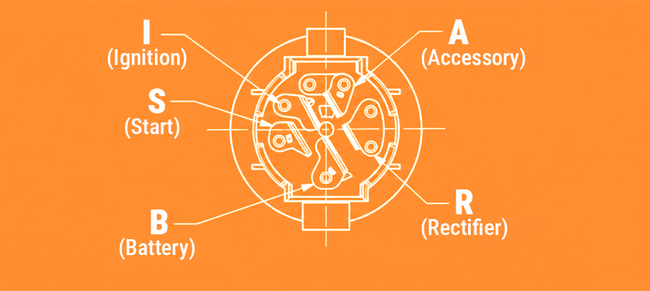
Toro Ignition Switch Wiring Connections
- B – Battery voltage in
- S – Starting circuit
- I – PTO switch
- A – Operator presence switch, safety interlock switches
- R – Regulator, charging circuit
How Does the Ignition Switch Work?
The ignition switch makes the proper connections for the starter, safety circuits, and accessories. Detents inside the switch control the three switch positions: OFF, RUN, and START. The START position is spring-loaded so that it automatically returns to the RUN position when released.
- Off Position (System Shutdown): In this position, the switch disconnects the battery voltage from all operational circuits. None of the terminals are connected. This ensures that the engine cannot be started, the battery does not drain and all safety/accessory systems are completely powered down.
- Run Position (Normal Operation): This is the position the key rests in while you are actively mowing. It powers up the mower’s essential operating systems. In the RUN position, the internal contacts bridge four key terminals together: B + R + I + A. This connects the Battery (B) to the Rectifier/Charging circuit (R) to keep the battery charging, the PTO Switch (I) to allow the cutting blades to engage, and the Safety Interlock/Operator Presence Switches (A) to ensure the mower runs only when it is safe (e.g., when you are sitting in the seat).
- Start Position (Engine Cranking): This position sends a temporary electrical signal to the starter solenoid to crank and fire up the engine. Since the Start position is spring-loaded, this means you must physically hold the key in this position against spring tension. The moment the engine catches and you let go of the key, it automatically snaps back to the RUN position. While you hold the key in START, the internal connection shifts to: B + R + I + S.
Notice that the Accessory/Safety circuit (A) is temporarily disconnected during cranking, and the Starting Circuit (S) is powered up. This sends battery voltage directly to the starter motor to crank the engine.
Why This Matters for Testing?
Understanding these positions is crucial because continuity testing is simply verifying if these internal connections are actually being made.
If you turn the key to RUN but your multimeter shows no connection between B and A, your safety circuits won’t get power, and the engine will immediately die.
If you turn the key to START but there is no connection between B and S, your starter motor will remain completely silent. Let’s grab a multimeter and test these connections step-by-step!
See complete guide on What Wire Goes to Ignition Switch?
Step-by-Step Guide on How to Test Your Toro Ignition Switch
Safety First
Before testing, do as follows for preparation:
- Stop the engine and pull out the switch for safety purposes
- Remove the control panel from the console
- Disconnect the harness from the ignition switch. Gently rock the connector back and forth until unplugged to avoid damage.
Set up Your Multimeter
- Prepare a digital multimeter
- Set the multimeter to the OHM or Continuity setting
Perform the Continuity Test
Now it’s time to perform the actual test.
Think of the ignition switch as a set of drawbridges. When the key is in a certain position, specific “bridges” must close to let electricity cross (this is called continuity). At the same time, other “bridges” must remain open to prevent electricity from going where it shouldn’t.
- When a connection is “Made” (Continuity exists): Your multimeter will beep, or show a very low resistance reading (close to 0 ohms).
- When a connection is “Open” (No continuity): Your multimeter will remain silent, and the screen will display OL (Open Loop) or 1 (infinite resistance).
The table below helps you better understand it.
| Key Position | Circuit “Make” | Expected Multimeter Reading |
|---|---|---|
| Off | None | OL(Open Loop)/ No Beep |
| Run | B+R+I+A | 0 ohms / Continuous Beep |
| Start | B+R+I+S | 0 ohms / Continuous Beep (Note: You must physically hold the key in START during this test) |
Symptoms of A Bad Mower Ignition Switch
Here are signs you may need to replace your Toro lawn mower ignition switch.
- No crank when the key is on
- Engine starts then stalls
- No power to accessories
- Key won’t turn
How to Replace the Ignition Switch on A Toro Riding Mower?
Tools and Materials Required
- Socket wrench set
- Screwdriver set
- Pliers
- Wire strippers
- Replacement ignition switch
- Wire connectors
- Electrical tape
Once you have gathered these tools and materials, you will be ready to replace the ignition switch on your riding mower.
Simple Steps on Ignition Switch Replacement
Here are simple steps to replace the ignition switch
- Disconnect the battery and spark plug to ensure safety
- Locate the ignition switch, usually near the steering column or on the dashboard
- Use a screwdriver or a wrench to remove any panels or covers
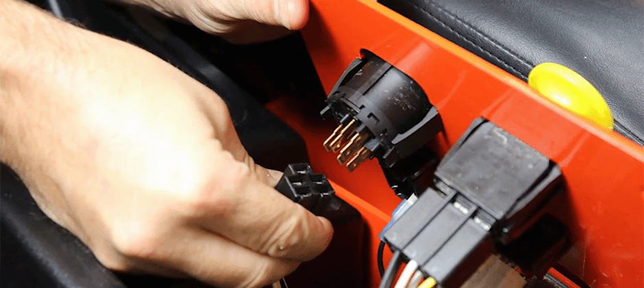
- Carefully disconnect the wiring harness connected to the back of the ignition switch
- Gently remove the harness by pressing the clip or unscrewing it
- Use the appropriate tool to loosen and remove the nut holding the ignition switch in place
- Remove the old ignition switch
- Carefully place the new ignition switch into the slot from which you removed the old one
- Use the retaining nut or screws that came with the new ignition switch to fasten it securely to the mower’s dashboard or console
- Reconnect the wiring harness to the new ignition switch. Match the wire connections to the labeled terminals on the back of the switch
- Double-check that all connections are tight to prevent any electrical issues once the mower is in operation
- Carefully tuck any excess wiring back into the dashboard or console
- Test the replacement ignition switch
What to Do after Ignition Switch Replacement?
To ensure the proper functioning of the replacement ignition switch, test it by turning the key and starting the riding mower. After installing the new ignition switch, it’s crucial to verify that it operates correctly before relying on it for regular use. Follow these steps to test the replacement ignition switch:
- Insert the key into the ignition switch to ensure the key fits snugly and turns smoothly
- Turn the key to the “ON” position to check if the dashboard lights and indicators are activated
- Engage the mower blades or attachments to see if they are properly engaged
- Turn the key to the “Starts” position to check if the engine starts smoothly
- Turn the key to the “Off” position to see if the engine shuts down without any issues
Final Words
Now, you’ve understood the Toro ignition switch wiring diagram and how to replace it on your riding mower. At FridayParts, you can source a vast range of lawn mower ignition switches to keep your Toro mower running at its optimal performance. With the right tools and materials, the process is simple and can be completed in no time. Remember to test the new ignition switch to ensure it’s working properly before using your mower. Enjoy the improved performance of your riding mower with the new ignition switch in place.
