
A single miswired terminal can leave your machine completely dead, or worse, cause electrical damage that costs far more than the switch itself. Whether you are replacing a faulty ignition switch or building a wiring setup, knowing exactly what wire goes to your ignition switch is the first step to getting it right. In this ignition switch wiring diagram guide, we will walk you through every terminal, every wire, and every key position, so you can wire your ignition switch safely, correctly, and with confidence.

What Is An Ignition Switch?
An ignition switch is the master control of your machine’s entire electrical system. It is the component that receives your key (or keyless signal) and determines which electrical circuits receive power and when. A faulty ignition switch can cause many problems, including:
- Engine failing to crank or start
- Electrical accessories cutting out while operating
- Unexpected machine misfire
- Starter motor running continuously
If you notice any of these symptoms, your ignition switch may need to be inspected or replaced. See Ignition Switch Failure Symptoms, Causes, and Fixes here.
How Does An Ignition Switch Work?
An ignition switch works by rotating through a series of positions, each of which controls a different set of electrical circuits. Most ignition switches have four key positions:
- OFF —Power is cut off. The key can be inserted or removed.
- ACC (Accessory) — Power is supplied to accessories such as the radio, lights, and instruments, but the engine remains off.
- ON (Run) — Full power is sent to all main electrical systems, including fuel, ignition, and gauges. This is the normal running position once the engine is started.
- START — A momentary position that sends a signal to the starter solenoid, which then engages the starter motor to crank and start the engine. The switch automatically returns to the ON position when released.
The table below breaks down exactly which terminals receive power at each key position, giving you a clear picture of how the ignition switch manages your machine’s electrical system.
| Switch Position | ACC | IGN | ST |
|---|---|---|---|
| ACC | On | Off | Off |
| IGN | On | On | Off |
| ST | Off | On | On |
As shown above, the ACC terminal powers down during the START position to reduce electrical load during engine cranking — a small but important design detail that protects your electrical system. In simple terms, the ignition switch performs three critical functions: controlling circuit power distribution, sending the start signal and protecting against unauthorized use. Shop high-grade ignition key switch here.
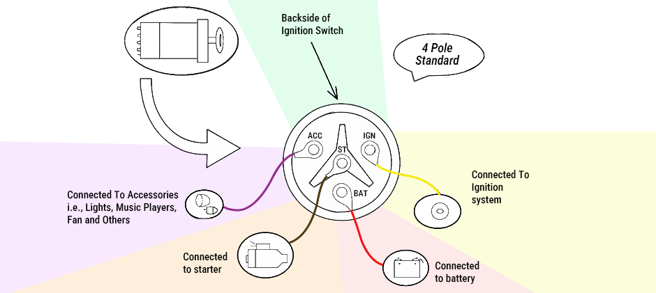
Diagram: What Wire Goes to Ignition Switch?
Understanding which wire connects to which terminal on your ignition switch is crucial for replacing or troubleshooting your ignition system. Whether you are working on a tractor, an excavator, or any other engine-powered machine, the basic wiring layout remains the same. Most standard ignition switches will have four core terminals, with each serving a specific function and connected to a specific wire in your electrical system. Generally, these four wires in the ignition switch are:
| Terminals | Full Name | Function |
|---|---|---|
| BAT | Battery | Receives constant power directly from the positive terminal of the battery. This terminal is always live, even when the key is off. |
| IGN | Ignition | Distributes power to the engine ignition system and other critical electrical components when the key is in the ON position. |
| ST | Starter | Sends a signal to the starter solenoid to engage the starter motor and crank the engine. This terminal is only active in the START position. |
| ACC | Accessory | Supplies power to non-essential accessories such as lights, radio, gauges, and wipers when the key is in the ACC position. |
What Color Are the Ignition Switch Wires?
Wire color is not universal. It depends on the make, model and manufacturer. It is thus essential that you go to where the wires are connected and not the colors. The following color conventions are commonly used as a general reference.
| Terminal | Common Wire Color |
|---|---|
| BAT | Red(thick gauge) |
| IGN | Red or Yellow |
| ST | Yellow or Brown |
| ACC | Purple or Orange |
*Note: Wire colors can differ significantly between brands and equipment models.
Never rely solely on wire color when wiring or replacing an ignition switch.
Always trace the wire back to its source or use a multimeter to verify which terminal carries what function.
How to Wire A Four-Terminal Ignition Switch?
Here’s a step-by-step guide to wiring the standard four-terminal ignition switch safely and correctly.
- Disconnect the battery: Always disconnect your battery’s negative (-) terminal before starting. This prevents electrical shocks, sparks, or accidental short circuits while wiring.
- Locate the ignition switch terminals: You can find four marked terminals at the back of your ignition switch.
- Connect the power(BAT): Use a 12-gauge wire to connect the BAT terminal on the ignition switch to the battery’s positive terminal or the main fuse box. This supplies electrical power to the switch, allowing it to distribute current to other circuits.
- Connect the Ignition(IGN): Then, attach a wire from the IGN terminal to the ignition coil, ECU, or engine management system. This circuit becomes active when the key is in the ON position, powering the ignition system, fuel pump, and other essential components.
- Connect the starter(ST): Connect the ST terminal to the starter solenoid. This wire only carries current when the key is turned to the START position. It engages the solenoid, which then activates the starter motor to crank the engine.
- Connect the accessories(ACC): Next, connect the ACC terminal to accessories such as the radio, fan or wipers. These accessories will work when the key is in the ACC or ON position, allowing you to use them without starting the engine.
- Ground the switch if required: Some ignition switches have a GND (ground) terminal. So, you should connect a black wire from this terminal to the chassis or a clean metal surface.
- Reconnect the battery and test: Reattach the negative (-) terminal of your battery when all wires are properly connected.
- Test key positions one by one: At last, you should test each key position to make sure everything works as it should.
During the process, you may have to refer to your manual to get each piece to fit back correctly again. Just be sure that you’re putting in the right components in the right place and that the screws, bolts, and clips are attached as suggested in the repair manual. Follow these steps, and you will successfully wire your ignition switch with minimal hassle.
Final Words
The ignition switch may be small, but it plays a critical role in your machine’s entire electrical system. Understanding its terminals, wire connections, and key positions gives you the foundation to confidently troubleshoot or replace it on any engine-powered equipment. Always trace the wire back to its source rather than relying on color alone, and test each key position after installation to ensure everything works correctly. We will be regularly updating this blog with ignition switch wiring diagrams for specific brands and models. Besides, we provide a vast selection of high-quality ignition switch replacements for various brands and equipment. Stay tuned to the FridayParts blogs so you never miss an update.
Related Articles You Might Also Like
5 Pole Ignition Switch Wiring Diagram
John Deere Ignition Switch Wiring Diagram
How Much Does It Cost to Make Ignition Switch Replacement?
Ignition Switch Problems: Symptoms, Causes, and Fixes