
This guide includes Ford ignition switch wiring color code and terminal diagrams to help you properly match factory wiring for reliable engine startup.
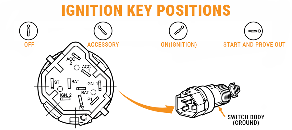
Decoding the Ignition Switch Terminals
Before reaching for the wire strippers, you must understand the terminal designations on the back of the Ford switch. Ford uses a specific set of labels that differ slightly from generic aftermarket switches.
- BAT: The main 12V constant power source directly from the battery.
- IGN 1 & IGN 2: Ignition feeds. IGN 1 typically handles the “Run” circuit, while IGN 2 powers the engine/coil during cranking and running.
- ACC 1 & ACC 2: Accessory feeds for the radio, heater, and AC blower motor.
- ST: The starter solenoid trigger circuit.
- P1 & P2: “Prove-out” circuits. These terminals provide a ground path to the switch body when the key is turned, momentarily lighting dashboard warning bulbs (Brake, Oil, Temp) to verify they aren’t burnt out.
Continuity Logic and Verification
Using a multimeter is non-negotiable for a professional install. Verify your switch logic matches the following requirements before making permanent connections:
| Key Position | Continuity Should Exist Only Between | Technical Note |
|---|---|---|
| Accessory | BAT and ACC 1 | Powers radio/accessories only. |
| Off | No continuity between any two terminals except BAT and BAT | Internal bussed lugs; all other circuits isolated. |
| On (Ignition) | Continuity should exist between any of the following terminals – BAT, ACC 1, ACC 2. IGN. 1. IGN. 2 | Full system power for operation. |
| Start | BAT and ST, BAT and IGN 1, BAT and IGN 2 | Cranking power while maintaining ignition. |
| Prove Out | P1 and Switch Body; P2 and Switch Body | Grounds warning circuits to test bulbs. |
Core Color Codes for Ford Ignition Systems
This table compiles factory wiring harness data for 1978–1979 Ford models. It is critical to understand that Ford’s wiring colors can vary between model years, vehicle models, and even different factory trim levels. Therefore, this table should be used as a reference, not as an absolute rule. Before cutting or splicing any wire, you must use a multimeter to verify its function against the continuity logic table in Section 2. Always trust your meter over the wire color.
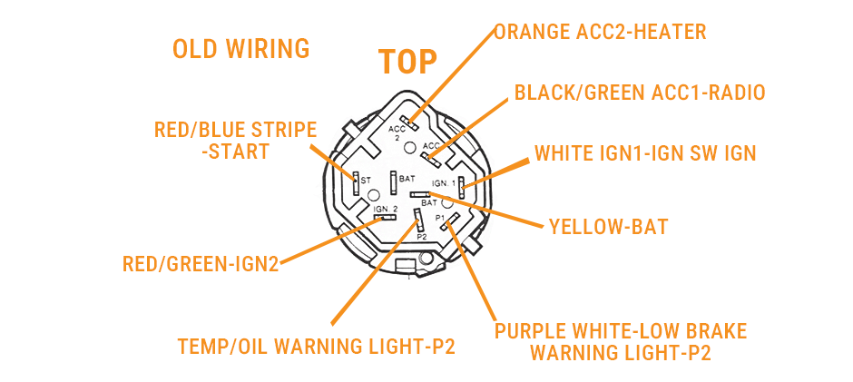
| Function | Factory Wire Color | Circuit Notes |
|---|---|---|
| Constant 12V | Yellow (x2 wires) | Main power feed to the switch. |
| Starter | Red/Blue Stripe | Triggers the starter solenoid. |
| Ignition 1 (Run) | Red/Light Green or White | Powers primary ignition systems. |
| Ignition 2 (Coil) | Gray/Yellow or Red/Green | Often two Gray/Yellow wires; powers coil. |
| Accessory 1 | Black/Light Green | Primary accessory/radio load. |
| Accessory 2 | Orange | High-draw blower motor circuit. |
| Brake Warning | Purple/White | Low brake warning light (P2). |
| Temp/Oil Warn | Red/White (Some models) | Dashboard warning light (P1). |
How to Wire a Universal Ignition Switch?
When adapting the factory harness shown in your diagram to a common 4-post universal switch (Battery, Ignition, Accessory, Start), you must consolidate multiple factory circuits from the original plug onto single terminals.
The Ignition Jump
Because universal switches typically have only one “IGN” post, you must connect both the White (IGN 1) wire and the Red/Green (IGN 2) wire from your factory harness to that same terminal on the new switch. This jump is critical to ensure all necessary circuits (like the primary ignition and the coil) receive power when the key is in the ‘ON’ or ‘RUN’ position, allowing the engine to remain running after you release it from ‘START’.
The Amperage Bottleneck
Accessory circuits (ACC 1 & ACC 2) and two Ignition circuits (IGN 1 & IGN 2) to manage current and heat. When you jump these to single posts on a universal switch, those terminals become bottlenecks for amperage and heat dissipation. Ensure your aftermarket switch is a high-quality unit rated for at least 30 amps to prevent terminal meltdown and potential fire.
Accessory Connections (ACC 1 & ACC 2)
Your harness has two accessory wires that must be connected to the single “ACC” post on the new switch: the Black/Green wire (ACC 1, for the Radio) and the Orange wire (ACC 2, for the Heater). You have two options for this:
- Simple Method (Use with Caution): You can connect both the Black/Green wire and the Orange wire to the single “ACC” post on the universal switch. Be aware this significantly increases the current load and heat at this terminal, compounding the “Amperage Bottleneck” issue. Only do this if you are confident your aftermarket switch can handle the combined load of the radio and the high-speed blower motor.
- Professional Method (Highly Recommended): For maximum reliability and safety, use a separate 30/40A automotive relay to power the high-draw heater/blower motor circuit (Orange wire). In this setup, the “ACC” post on your ignition switch is used only to trigger the relay (pin 86). The blower motor’s power is then drawn directly from a fused battery source through the relay’s high-current contacts (pins 30 and 87). This isolates the heavy load from the ignition switch, preventing overheating and ensuring longevity.
Isolating Unused Wires
The original factory connector has wires for functions not present on a simple 4-post switch. Based on the diagram, these include the wires for the TEMP/OIL WARNING LIGHT and the LOW BRAKE WARNING LIGHT (both connected to the P2 terminal). These warning light circuits are separate from the main ignition functions. It is crucial to identify and insulate these wires individually, for instance, by capping them or using heat shrink tubing. This prevents them from accidentally grounding or causing short circuits.
Critical Installation Techniques
Reliability in automotive electrical systems is built on the quality of the mechanical connection. As a specialist, I mandate the following:
- Pigtail Retention: Original factory plugs for Ford switches are rarely remanufactured. Keep your original pigtail, cutting the wires 3-4 inches back to allow for a clean, manageable splice.
- Professional Splicing: Avoid “vampire” clips or twist-and-tape methods. Use uninsulated butt connectors protected by marine-grade heat shrink. This creates a moisture-proof, vibration-resistant joint.
- Controlled Heat: Use a heat gun rather than a torch. Torches create localized hot spots that can crystallize wire insulation over time, leading to future cracks, brittle wires, and dangerous shorts.
Troubleshooting: The “Runaway Engine” Scenario
Safety Warning: If your engine keeps running after you pull the key out, the alternator is sending power backward into the ignition circuit. Disconnecting the battery negative cable won’t shut it off—the alternator is powering the motor on its own.
Quick Emergency Fix: Put thick rubber gloves on first to avoid high voltage sparks. Unplug the thick ignition coil wire running to the distributor to cut spark and kill the engine.
If you don’t want to mess with high voltage parts, there’s a safer mechanical trick: grab a thick rag or chunk of wood and tightly plug the air intake opening on your air filter housing or carb/throttle body. The engine runs out of oxygen and dies in seconds, zero shock risk.
How to Fix the Root Issue: This issue means your ignition circuit stays powered nonstop. Double-check IGN 1 and IGN 2 only get power when the key sits at On or Start. You might need a diode or relay to stop the alternator exciter wire from sending power back to the ignition coil.
Conclusion
The color codes are a helpful guide, but don’t rely on them alone. Before making any final connections, use a multimeter to verify each circuit based on the terminal functions listed above.
Need replacement ignition parts or wiring harnesses? FridayParts offers a wide range of reliable ignition switches with broad equipment compatibility. Keep your Ford running the way it should.