

A starter solenoid wiring diagram is crucial for troubleshooting or repairing the starting system of your tractor. For farmers and equipment operators, a tractor that won’t start during planting or harvest season can mean costly delays and lost productivity. Whether you’re an experienced DIYer or a farm owner trying to diagnose your tractor, understanding the basics of the starter solenoid can save you energy, time and money. In this guide, we’ll give insights into how a tractor starter solenoid works, how it is wired and tips to diagnose common electrical issues yourself. Let’s get started!
What Is A Starter Solenoid?
Before jumping into the starter solenoid wiring diagram, it’s helpful to understand what a starter solenoid actually is. A starter solenoid, aka a solenoid switch or a solenoid, is a magnetically actuated switch attached to the start motor, which spins the engine to start. Think of the solenoid as the relay or switch that controls power flow from your equipment’s battery to the starter motor.
Agricultural tractors, particularly those powered by diesel engines, place especially high demands on the starter solenoid. Diesel engines have higher compression ratios than gasoline engines, which means the starter motor must work harder to crank the engine. This results in higher current demands and greater stress on the solenoid. When you turn the ignition key, the solenoid receives a small electrical signal that triggers it to close a circuit, allowing a large current to flow and crank the engine. Without a functioning starter solenoid, your tractor won’t start, leaving you stranded in the field when you need it most.
Why Does Proper Starter Solenoid Wiring Matter?
Good starter solenoid wiring is very important for the starter solenoid and starter motor. A well-wired solenoid gives the starter motor full power every time. This keeps the starter motor and other parts safe from damage. Good wiring also stops problems like overheating or shorts. Reliable wiring helps the starter motor and solenoid work together, so the vehicle starts well every time.
But if wires are not hooked up right, the starter motor may not get enough power. As a result, you’ll feel your engine reluctant to start or a weak starter motor. If the power is weak or unsteady, the solenoid may not close the circuit. This can block the current to the starter motor and make your engine hard to start. If two solenoids share a circuit but are wired wrong, one might not work. Electricity can flow back from one solenoid to another, so experts say to use diodes or separate wires.
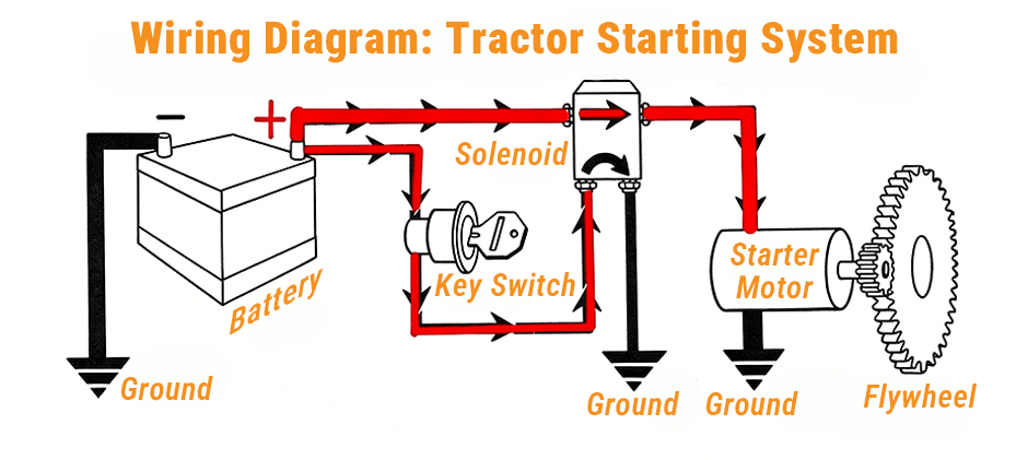
Starter Solenoid Wiring Diagram
A starter switch wiring diagram shows how to connect wires. It uses symbols and numbers for each terminal. Each terminal has a label like B for battery, S for start, M for motor, R for relay, and I for ignition. These labels make it easier to install and fix problems.
The diagram below shows the complete wiring layout of a tractor starting system, including all key components and two separate electrical circuits that work together to start the engine. The starting system is built around two distinct circuits:
- The Main Circuit (thick red line) — a heavy-gauge cable that runs directly from the battery positive terminal to the solenoid, and from the solenoid to the starter motor. This circuit is always live the moment the battery is connected. No switch sits between the battery and starter motor in this path.
- The Control Circuit (thin red line) — a smaller gauge wire that runs from the battery positive terminal, through the key switch (ignition switch), and to the solenoid’s control terminal. This circuit only carries current when you turn the key to START.
It also shows three separate ground points — at the battery, the solenoid and the starter motor. All these points connect to the tractor chassis. The chassis itself serves as the return path that completes both circuits. The diagram includes the following key components:
- Battery: Supplies the electrical power.
- Starter Solenoid: Acts as an electrical switch to engage the starter motor.
- Starter Motor: Engages the engine flywheel to start the engine.
- Ignition Switch: Sends the signal to the solenoid when you turn the key.
- Flywheel: Engages with the starter motor’s gear teeth to crank the engine.
Solenoid Terminal Functions and Identification
Each terminal on the starter solenoid serves a specific function.
- The battery terminal (B) connects to the battery’s positive side.
- The start terminal (S) connects to the ignition switch.
- The motor terminal (M) links to the starter motor.
Some solenoids have extra terminals like R (relay) or I (ignition). These extra terminals help with other circuits. Below are the common wire color codes that help match wires to the right terminal. The colors vary depending on the model year, make, and model.
How to Wire the Starter Solenoid with Diagram?
There are usually four terminals on a tractor solenoid. You should use the two large terminals for battery power and starter motor connection and the other two small terminals for solenoid coil control circuit, usually to the ignition switch and ground.
Knowing which terminal is which helps avoid confusion during troubleshooting or installation. Also, you can use the color codes to indicate wire functions, as specified in the table below.
| Terminal/Function | Common Wire Color |
|---|---|
| Battery (B) | Red |
| Start (S) | Yellow or Purple |
| Motor (M) | Black |
| Relay (R) | Blue |
| Ignition (I) | Brown |
| Ground | Green or Bare |
Basic Wiring Flow
- The battery positive terminal connects via heavy gauge cable to the large B terminal on the solenoid
- The large M terminal on the solenoid connects to the starter motor
- The key switch sends a small control current to the small S terminal on the solenoid
- When the key is turned to START, the solenoid’s internal coil energizes, simultaneously closing the main circuit contact points AND pushing out the starter gear to mesh with the flywheel
- High current flows from the battery through the solenoid to the starter motor, cranking the engine
- All three components — battery, solenoid, and starter motor — return current to the battery negative terminal via the chassis ground
- Safety switches such as the PTO switch, seat switch, or neutral safety switch may be wired into the control circuit between the key switch and the solenoid. If any safety switch is open, the control signal never reaches the solenoid and the engine will not crank.
Tips for Wiring or Replacing the Starter Solenoid
If you’re installing a new solenoid or rewiring the starter system, follow these steps:
- Disconnect the Battery First: Always disconnect the negative battery terminal before working on electrical components to avoid shorts or shocks.
- Use the Correct Wire Gauge: Starter circuits draw high current, so use appropriately thick wires (usually 10-12 gauge) for the battery and starter connections to prevent overheating.
- Secure and Insulate Connections: Make sure all terminals are tight and insulated with heat shrink tubing or electrical tape to prevent corrosion and accidental shorts.
- Follow the Manufacturer’s Wiring Diagram: Even though many solenoids share similar wiring principles, always refer to your machine’s specific wiring diagram to ensure proper connections and safety compliance.

Additional Electrical Components Related to the Starter Circuit
You must understand other related parts in the diagram when focusing on the starter solenoid wiring.
Ignition Switch
The ignition switch controls power to the solenoid coil. It often has multiple positions such as OFF, RUN, and START. The wiring diagram will show how the ignition switch feeds the solenoid and other systems like the ignition coil and fuel pump. See Ignition Switch Wiring Diagram here.
Battery and Ground Connections
Reliable grounding is essential for the starter circuit. The battery negative terminal should be connected securely to the mower’s frame. Similarly, the solenoid and starter motor grounds must be solid and free of corrosion.
Bad Starter Solenoid Symptoms and Causes
The following table shows the common issues related to the starter solenoid wiring.
| Problems | Causes | Actions |
|---|---|---|
| Tractor won’t start but battery is good | A faulty solenoid | Test with multimeter and wiring diagram |
| Clicking noise when trying to start | Corroded or loose wiring connections; Faulty solenoid coil; Safety switches interrupting the circuit |
Reviewing the wiring diagram helps you pinpoint where the breakdown occurs |
| Starter runs continuously after releasing the key | The solenoid contacts might be sticking closed | Checking the wiring and solenoid operation according to the diagram |
Where to Find Starter Solenoid Wiring Diagram?
Searching for the right wiring diagram for your tractor is key to effective troubleshooting. You can find it from the following sources:
- Owner’s Manual: Many manufacturers include wiring diagrams in the manual.
- Service Manuals: Detailed repair manuals often have comprehensive schematics.
- Manufacturer Support: Contacting the brand’s customer service can sometimes yield official wiring documentation.
- Online Forums and Websites: Hobbyist and professional forums frequently share wiring diagrams and troubleshooting tips.
Final Words
Understanding the starter solenoid wiring diagram is essential to troubleshooting and maintenance of your tractor. By knowing how the solenoid interacts with other key components, you can confidently diagnose your starting issue and do a replacement. Always keep this in mind: use the right tools and refer to your equipment’s specific wiring diagram to ensure safe and reliable mowing. At FridayParts, you can source a vast selection of quality starter solenoids to keep your machine at its best performance.
Related Articles
5 Signs of a Bad Starter Solenoid You Can’t Ignore
