

The Massey Ferguson’s fuse box is the central hub for distributing power and protecting the electrical components. When you run into electrical problems, the fuse box is always the first place to look at. Understanding how to read a Massey Ferguson fuse box diagram can help you troubleshoot and fix electrical system problems, saving you a lot of effort and time. In this guide, we’ll dive into the fuse box diagram for MF 6400 as an example to help you better understand the fuse box.
What Is A Fuse Box Diagram?
The primary role of a fuse box is to prevent electrical overloads and protect a car’s circuits from damage. Fuse electrical symbols in circuit diagrams represent fuses and their role in protecting circuits from overcurrent and short circuits. These standardized symbols help engineers and technicians quickly understand circuit protection without viewing the physical fuse. When you run into electrical problems, the fuse box is often the first place to look at. Now, let’s get started to explore the diagram for Massey Ferguson.
Massey Ferguson Fuse Box Diagram Explained
In this part, we’ll present a fuse box diagram of Massey Ferguson 6400 for your reference. Since the fuses may vary on different models, always refer to your owner’s manual before taking any actions.
Fuse Sizes & Color of Massey Ferguson Fuse Box
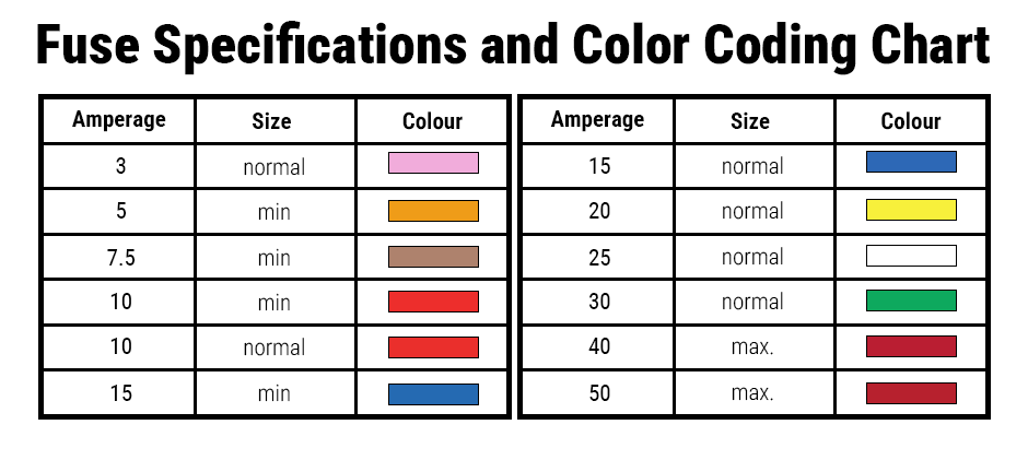
To understand the Massey Ferguson diagram, you must know the fuse symbols, sizes and color codes. The fuse elements are named depending on their function:
- F= Fuse
- SH= Shunt (shunts are fuses)
- R= Relay
These fuses are of different powers and sizes. To help you better identify the fuse according to the fuse color and specifications, see the Fuse Specifications and Color Coding Chart below.
Massey Ferguson Fuse Box Diagram (Version for North America)
Here we’ll walk you through the fuse box diagram for Massey Ferguson 6400 and the function of each fuse in the diagram. Let’s get started!
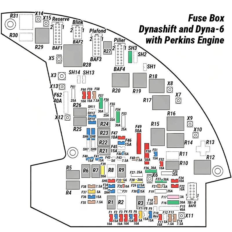
See the full table indicating the fuse allocations in Appendix 1.
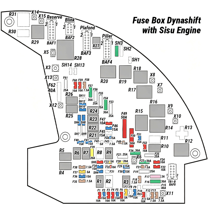
The table in Appendix 2 shows you the details.
Step-by-Step Guide to Reading A Fuse Box
Reading the fuse box involves the following steps:
- Locate the fuse box: To find where the fuse box is located, you should consult your owner’s manual for the exact location of the main fuse box and any secondary fuse panels. In most cases, the main fuse box is situated under the hood, near the battery, while secondary panels can be found in the passenger compartment, often hidden behind a removable panel.
- Interpret the fuse box diagram: Once you’ve located the fuse box, you must open the cover for the diagram on the inside. This diagram shows the location and purpose of each fuse within the box. You should take a moment to familiarize yourself with the layout and the various components protected by each fuse. You can refer to the owner’s manual for a more detailed schematic if the diagram is missing or unclear.
- Identify fuse types and conditions: Fuses come in different types, such as blade fuses, glass tube fuses and cartridge fuses. Blade fuses are color-coded according to their amperage rating, which appears on the fuse itself. To check for a blown fuse, you can look for a broken wire inside the transparent housing or use a multimeter to test for continuity.
- Replace a blown fuse: If a fuse has blown, replacing it with one of the same amperage rating is crucial. Using a fuse with a lower amperage can cause it to blow prematurely, while a higher amperage fuse may allow the connected component to become damaged before the fuse blows. To replace the fuse, you must carefully remove it using fuse pliers or your fingers and insert the new fuse securely into the same slot.
Wrapping up
Knowing how to read a fuse box diagram is a crucial skill when it comes to tackling electrical problems of your Massey Ferguson. You can troubleshoot and repair these electrical problems easily with the diagram. At FridayParts, you can get a vast range of quality fuses and relays and explore a great deal of knowledge about your Massey Ferguson electrical system. Stay tuned to our blogs and start your exploration now.
Related Articles You Might Enjoy
Freightliner M2 Fuse Box Diagram
Appendix
1 Fuse Box – Dynashift and Dyna-6 with Perkins Engine
| Ref. | Amp. | Size | Protected function |
|---|---|---|---|
| F1 | 10 | min. | Front right-hand and rear left-hand side lights, backlighting of switches / console / cigarette lighter |
| F2 | 15 | min. | Roof direction indicators |
| F3 | 10 | min. | Left-hand fender extension direction indicator |
| F4 | 10 | min. | Auto III (Dynashift), Auto V (Dyna-6), instrument panel, gearbox / differential / 4WD / PTO / creeper unit neutral switch |
| F5 | 15 | min. | Stop lights |
| F6 | 10 | min. | Controls on armrest (with Auto V) |
| F7 | 5 | min. | Electronic injection control unit (ECU) control relay, reversing light relay |
| F9 | 15 | min. | Suspended front axle and front PTO |
| F11 | 10 | min. | Air conditioning compressor |
| F13 | 7.5 | min. | Work headlights module |
| F14 | 7.5 | min. | Electrical rear view mirrors |
| F16 | 30 | normal | Injection pump stop solenoid valve, braking pressure sensor |
| F17 | 3 | normal | Brake switch |
| F18 | 7.5 | min. | Linkage, diagnostics, braking circuit pressure sensor |
| F19 | 25 | normal | Pneumatic seat, fuel heater |
| F21 | 7.5 | min. | Linkage, Datatronic 3 |
| F22 | 10 | min. | TOC/BOC pedal switch, buzzer, start switch, reverse shuttle lever, throttle pedal position sensor, armrest, parameter display selector switch |
| F23 | 30 | normal | Cigarette lighter, radio, roof light |
| F24 | 10 | min. | Right-hand fender extension direction indicator |
| F25 | 25 | normal | Hazard warning light switch, permanent 12 V |
| F26 | 30 | normal | Power socket |
| F27 | 25 | normal | Electronic injection control unit (ECU) |
| F28 | 20 | normal | Electronic injection control unit (ECU) |
| F29 | 15 | min. | Auto III and Auto V calculators (Dyna-6) |
| F30 | 15 | min. | Electronic injection control unit (ECU) |
| F32 | 10 | min. | Electronic injection control unit (ECU) |
| F33 | 5 | min. | Electronic injection control unit (ECU) - Thermostat |
| F34 | 15 | min. | Dipped lights |
| F35 | 7.5 | min. | Horn |
| F36 | 15 | min. | Headlights |
| F37 | 5 | min. | Clutch safety start switch |
| F38 | 7.5 | min. | Front left-hand and rear right-hand side light, instrument panel backlighting |
| F39 | 20 | normal | Side / road lights switch on handrails |
| F40 | 15 | min. | Left-hand direction indicator |
| F41 | 15 | min. | Joystick |
| F44 | 15 | min. | Right-hand direction indicator |
| F46 | 15 | min. | Rear windscreen wiper, heating |
| F47 | 10 | min. | Radio |
| F48 | 7.5 | min. | Suspended front axle |
| F49 | 50 | max. | Cab suspension |
| F50 | 50 | max. | Air conditioning |
| F51 | 15 | min. | Instrument panel |
| F52 | 10 | min. | Power socket |
| F53 | 25 | normal | Front windscreen wiper |
| F54 | 30 | normal | Front work headlights |
| F55 | 25 | normal | Rear work headlights |
| F56 | 25 | normal | Work headlights on rear fenders and/or handrails |
| F57 | 30 | normal | Footstep work headlights |
| F58 | 7.5 | min. | Work headlights module |
| F59 | 10 | min. | Flashing beacon |
| F60 | 10 | min. | #ERROR! |
| F61 | 25 | normal | Hazard warning lights |
| SH3 | 30 | normal | Work headlights on footsteps and handrails |
| SH4 | 15 | min. | Headlights |
| SH5 | 10 | min. | Dipped lights |
| SH6 | 10 | normal | Direction indicator |
| SH8 | 10 | min. | Direction indicator |
| SH10 | 15 | min. | Direction indicator |
| SH12 | 15 | min. | Direction indicator |
| R1 | / | / | Handrail road lights |
| R3 | / | / | Electronic injection control unit (ECU) |
| R4 | / | / | Reversing light |
| R5 | / | / | Stop lights |
| R6 | / | / | 1st additional ON/OFF spool valve |
| R7 | / | / | 2nd additional ON/OFF spool valve |
| R9 | / | / | Electronic injection control unit (ECU) |
| R10 | / | / | Power socket |
| R12 | / | / | Wiper timer |
| R14 | / | / | Air conditioning |
| R15 | / | / | #ERROR! |
| R16 | / | / | Cab suspension (optional) |
| R17 | / | / | Front work headlights |
| R18 | / | / | Rear work headlights |
| R19 | / | / | Rear fender work headlights |
| R20 | / | / | Footstep work headlights |
| R21 | / | / | Left-hand direction indicator |
| R22 | / | / | Direction indicator and brake light on left-hand fender extension |
| R23 | / | / | Direction indicator and brake light on right-hand fender extension |
| R24 | / | / | Right-hand direction indicator |
| R25 | / | / | Right-hand direction indicator on rear fender |
| R26 | / | / | Left-hand direction indicator on rear fender |
| R27 | / | / | Flashing beacon |
| R28 | / | / | Hazard warning light |
| R29 | / | / | Air conditioning compressor |
2 Fuse Box – Dynashift with Sisu Engine
| Ref. | Amp. | Size | Protected function |
|---|---|---|---|
| F1 | 10 | min. | Front right- and rear left-hand side lights, back-lighting of switches / console / cigarette lighter |
| F2 | 15 | min. | Roof direction indicators |
| F3 | 10 | min. | Left-hand fender extension direction indicator |
| F4 | 10 | min. | Auto III, instrument panel, gearbox / differential / 4WD / PTO / creeper unit neutral switch |
| F5 | 15 | min. | Stop lights |
| F6 | 10 | min. | Controls on armrest (with Auto V) |
| F7 | 5 | min. | Electronic injection control unit (ECU) control relay, reversing light relay |
| F9 | 15 | min. | Suspended front axle and front PTO |
| F11 | 10 | min. | Air conditioning compressor |
| F13 | 7.5 | min. | Work headlights module |
| F14 | 7.5 | min. | Electrical rear view mirrors |
| F16 | 30 | normal | Injection pump solenoid valve, braking pressure sensor |
| F17 | 3 | normal | Brake switch |
| F18 | 7.5 | min. | Lamp diagnostics, braking circuit pressure sensor |
| F19 | 25 | normal | Pneumatic seat, fuel heater |
| F21 | 7.5 | min. | Linkage, Datatronic 3 |
| F22 | 10 | min. | TOC/BOC pedal switch, buzzer start switch, reverse switch, throttle pedal position sensor, author light / parameter display selector switch |
| F23 | 30 | normal | Cigarette lighter, radio, roof light |
| F24 | 10 | min. | Right-hand fender extension direction indicator |
| F25 | 25 | normal | Hazard warning light switch, permanent 12 V |
| F26 | 30 | normal | Power socket |
| F28 | 20 | min. | Electronic injection control unit (ECU) |
| F29 | 15 | min. | Auto III calculator |
| F30 | 15 | min. | Electronic injection control unit (ECU) |
| F31 | 15 | min. | Sisu ECM module |
| F32 | 10 | min. | Electronic injection control unit (ECU) |
| F34 | 15 | min. | Dipped lights |
| F35 | 7.5 | min. | Horn |
| F36 | 15 | min. | Headlights |
| F37 | 5 | min. | Clutch safety start switch |
| F38 | 7.5 | min. | Front left and rear right-hand side light, instrument panel back lighting |
| F39 | 20 | normal | Side / road lights switch on handrails |
| F40 | 15 | min. | Left-hand direction indicator |
| F41 | 15 | min. | Joystick |
| F42 | 5 | min. | Sisu ECU |
| F44 | 15 | min. | Right-hand direction indicator |
| F46 | 15 | min. | Rear windscreen wiper, heating |
| F47 | 10 | min. | Radio |
| F48 | 7.5 | min. | Suspended front axle |
| F49 | 50 | max. | Cab suspension |
| F50 | 50 | max. | Air conditioning |
| F51 | 15 | min. | Instrument panel |
| F52 | 10 | min. | Power socket |
| F53 | 25 | normal | Front windscreen wiper |
| F54 | 30 | normal | Front work headlights |
| F55 | 25 | normal | Rear work headlights |
| F56 | 25 | normal | Work headlights on rear fenders and/or handrails |
| F57 | 30 | normal | Footstep work headlights |
| F58 | 7.5 | min. | Work headlights module |
| F59 | 10 | min. | Flashing beacon |
| F60 | 10 | min. | #ERROR! |
| F61 | 25 | normal | Hazard warning lights |
| SH3 | 30 | normal | Work headlights on footsteps and handrails |
| SH4 | 15 | min. | Headlights |
| SH5 | 10 | min. | Dipped lights |
| SH6 | 10 | normal | Direction indicator |
| SH8 | 10 | normal | Direction indicator |
| SH10 | 15 | min. | Direction indicator |
| SH12 | 15 | min. | Direction indicator |
| R2 | / | / | Electronic injection control unit (ECU) |
| R3 | / | / | Electronic injection control unit (ECU) |
| R4 | / | / | Reversing light |
| R5 | / | / | Stop lights |
| R6 | / | / | 1st additional ON/OFF spool valve |
| R7 | / | / | 2nd additional ON/OFF spool valve |
| R10 | / | / | Power socket |
| R12 | / | / | Wiper timer |
| R14 | / | / | Air conditioning |
| R15 | / | / | #ERROR! |
| R16 | / | / | Cab suspension (optional) |
| R17 | / | / | Front work headlights |
| R18 | / | / | Rear work headlights |
| R19 | / | / | Rear fender work headlights |
| R20 | / | / | Footstep work headlights |
| R21 | / | / | Left-hand direction indicator |
| R22 | / | / | Direction indicator and brake light on left-hand fender extension |
| R23 | / | / | Direction indicator and brake light on right-hand fender extension |
| R24 | / | / | Right-hand direction indicator |
| R25 | / | / | Right-hand direction indicator on rear fender |
| R26 | / | / | Left-hand direction indicator on rear fender |
| R27 | / | / | Flashing beacon |
| R28 | / | / | Hazard warning light |
| R29 | / | / | Air conditioning compressor |
