

Understanding the fuse box diagram is one of the most common concerns among many truck owners, mechanics and fleet managers seeking quick access to electrical components for maintenance and repairs. In this guide, we’ll walk you through the Kenworth T680 fuse box diagram, fuse panel locations and how you can do a DIY replacement. Enjoy your reading.
What Is A Kenworth Fuse Box?
The Kenworth fuse box or fuse panel is a crucial element in the truck’s electrical system. It serves as a safeguard for circuits that power everything from lights and gauges to engine control modules. The main functions of the Kenworth fuse box are:
- Prevents damage caused by overloads or short circuits.
- Helps identify and replace faulty fuses
- Facilitates adding or modifying electrical components safely.
Understanding the location and layout of the fuse panel ensures that owners and technicians can quickly address electrical issues, minimize downtime, and maintain optimal truck performance.
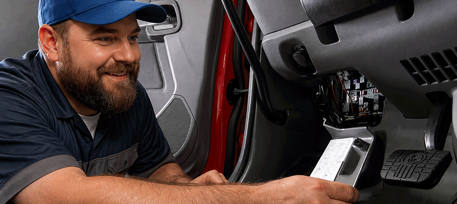
Where to Locate the Fuse Box on Your Kenworth Truck?
Knowing the exact location of the fuse panels in your Kenworth truck can save time, reduce frustration, and help ensure that your vehicle operates smoothly. While Kenworth trucks come in various models, such as T680, W990, T880, and more, with varied designs, the common locations for Kenworth fuse boxes are as follows:
- Under the driver’s side dashboard or near the kick panel
- In the engine compartment
- In the center console or behind interior panels
- Under the hood or near the battery
- On the firewall or near the batteries
How to Find Kenworth Fuse Box Diagram?
Here are some simple ways to find the fuse box diagram for your Kenworth truck.
- Consult the owner’s manual: It provides detailed diagrams and location maps for fuse panels.
- Look for visual clues: Fuse boxes are often marked with symbols or labels, such as “FUSE” or “POWER DISTRIBUTION.” Covers may have transparent windows or labels indicating their purpose
- Check online resources and forums: Manufacturer websites or dedicated Kenworth forums often include diagrams and user experiences
Understanding the Kenworth Fuse Box Diagram
Most Kenworth fuse panels have a diagram that indicates the function of each fuse and relay. Getting familiar with the diagram allows for quick diagnosis.
How to Identify the Kenworth Fuse Box Diagram?
To identify the diagram, you must follow:
- Locate the diagram: Usually printed on the inside of the fuse panel cover or on an adjacent sticker
- Identify circuits: Such as headlights, ABS, engine control, radio, auxiliary power, etc
- Understand fuse sizes: Be aware of the amperage ratings and replace with identical fuses.
Understanding the fuse layout minimizes errors and ensures the integrity of the electrical system.
Additional Electrical Components in Kenworth Fuse Panels
Beyond standard fuses, these panels may house relays, circuit breakers, and control modules:
- Relays: Used for switching higher current loads, like fuel pumps or cooling fans.
Circuit Breakers: Resettable protection devices that serve as alternatives to traditional fuses.
Control Modules: Integrated electronic units that manage specific systems, often accessible via fuse panels.
Knowing these components enhances troubleshooting efficiency and helps diagnose complex electrical issues.
Kenworth T680 Fuse Box Diagram
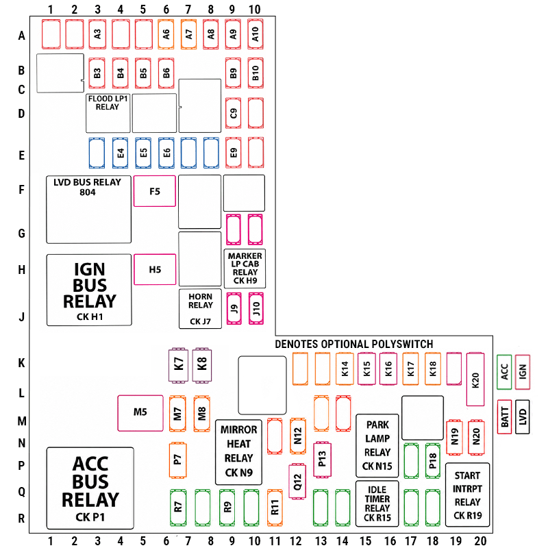
| Fuse | Amp | Description | Fuse | Amp | Description | Fuse | Amp | Description | Fuse | Amp | Description |
|---|---|---|---|---|---|---|---|---|---|---|---|
| A1 | 15 | Flood LP2 | E5 | 15A | Power Port 2 | K14 | 10 | SUSP/Chaisis | P7 | 15 | Air Dryer |
| A3 | 15 | Flood LP1 | E6 | 10A | Cab Dome Lamp | K15 | 10 | MISC LOW CURR | P13 | 10 | Key PWR SW |
| A6 | 10A | Body Ignition PWR | E9 | 10A | Telematics | K16 | 10 | Park LP-Cab | P14 | 10 | Digi Display PWR2 |
| A7 | 10A | RP1266 IGN | F5 | 30 | RH Door Mod | K17 | 5 | VECU/CECU IGN PWR | P18 | 5A | HVAC Head – 5A ACC |
| AS | 10A | RP1226 BATT | H5 | 30 | LH Door Mod | K18 | 5 | RH Stalk Shifter | R8 | 10A | QCOM/LDWS/RM DIAG |
| 83 | 10A | Gauge Cluster | J9 | 5 | Diagnostic Power | K20 | 30 | TRLR Hotline | R9 | 5A | VECU/CECU ACC PWR |
| B4 | 10A | VECU BATT PWR 2 | J10 | 5 | VECU LVD Sense | M7 | 10 | Splice Feed, IGN | R14 | 15A | Spare ACC SW1/SW2 |
| B6 | 15 | Paccar AMT BATT | K7 | 10 | Horn | N11 | 15 | RH Mirror | R18 | 10A | Radio Wakeup |
| C9 | 15 | CB/Radio Power | KB | 10 | Cab Marker Lamp | N19 | 15 | LH Mirror | – | – | – |
| E4 | 15 | Power Port 1 | K12 | 25 | ENG MTD Fuel Heater | N20 | 15 | Park LP-TRLR | – | – | – |
Common Kenworth Electrical Problems
Common electrical issues related to the Kenworth T680 fuse box are:
- Blown fuses due to electrical overloads or short circuits
- Corrosion or dirt accumulation in fuse sockets
- Loose connectors due to vibration
- Damaged fuse holders
- Faulty relays or control modules
Tips for Troubleshooting
- Always check the fuse first for blowing or corrosion when electrical components fail
- Inspect the fuse holder for signs of corrosion or damage
- Check wiring harnesses for damage or loose connectors
- Replace faulty fuse holders or connectors if necessary
- Use OEM or equivalent parts for reliable repairs
- Use a multimeter or fuse tester to verify continuity
Regular inspection and maintenance of fuse panels can prevent unexpected electrical failures
Step-by-Step Guide to Replace Fuses
Once you’ve located the fuse panel, follow these safety tips and procedures:
Safety First
- Turn off the engine and remove the key
- Disconnect the battery if working on high-current circuits
- Use insulated tools to prevent accidental shorts
- Wear safety gloves and goggles if necessary
Accessing the Fuse Panel
- Remove any covers or panels securing the fuse box
- Use the fuse diagram (usually inside the cover) to identify the fuse you need
- Gently pull out the fuse using a fuse puller or tweezers
Replacing the Fuse
- Inspect the blown fuse for a broken wire or burn marks
- Replace with a fuse of the same amperage rating
- Reinstall the fuse securely
- Replace the cover or panel
Testing
- Turn on the vehicle and check if the component functions properly
- Use a multimeter to verify fuse continuity if needed
Wrapping up
Understanding the Kenworth fuse box diagram is the very first step for truck DIYers who run into electrical problems. Finding the exact fuse panel location and knowing the function of each fuse can save plenty of time and minimize downtime. At FridayParts, you can learn more about electrical parts troubleshooting, repair and maintenance through our blogs and source an extensive selection of quality fuses, relays & contactors and other Kenworth truck replacement parts. Enjoy your smooth operation on the road.
