

The correct valve setting is not universal. It depends on the engine series, valve design, and sometimes the crankshaft layout. Get it wrong, and you’ll see hard starting, weak power, or excess valve noise. This guide uses the Briggs & Stratton valve clearance chart to help you find the right intake and exhaust specs quickly. It also covers the most common setup mistakes.
Briggs & Stratton Valve Clearance Chart by Engine Family
A Briggs & Stratton valve clearance chart only works if the engine family is matched correctly first. Some series use L-head layouts, others use OHV designs, and several have different values for horizontal and vertical shaft versions.
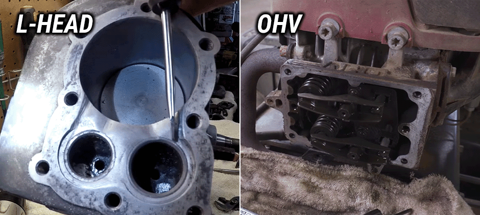
L-Head Aluminum/Cast Sleeve Single Cylinder
| Model Series | Intake Clearance | Exhaust Clearance |
|---|---|---|
| 60000, 80000, 90000, 10A000 thru 10M000, 110000, 120000 | 0.12 / 0.18 mm (approx. 0.005 / 0.007 in.) | 0.18 / 0.23 mm (approx. 0.007 / 0.009 in.) |
| 130000, 170000, 171700, 190000, 191700, 280000 | 0.12 / 0.18 mm (approx. 0.005 / 0.007 in.) | 0.23 / 0.28 mm (approx. 0.009 / 0.011 in.) |
| 220000 / 250000 | 0.12 / 0.23 mm (approx. 0.005 / 0.009 in.) | 0.23 / 0.28 mm (approx. 0.009 / 0.011 in.) |
L-Head Cast Iron Single Cylinder
| Model Series | Intake Clearance | Exhaust Clearance |
|---|---|---|
| 230000, 240000, 320000 | 0.18 / 0.23 mm (approx. 0.007 / 0.009 in.) | 0.43 / 0.48 mm (approx. 0.017 / 0.019 in.) |
L-Head Opposed Twin Cylinder
| Model Series | Intake Clearance | Exhaust Clearance |
|---|---|---|
| 400000, 420000, 460000 | 0.10 / 0.15 mm (approx. 0.004 / 0.006 in.) | 0.18 / 0.23 mm (approx. 0.007 / 0.009 in.) |
OHV Single Cylinder
| Model Series | Intake Clearance | Exhaust Clearance |
|---|---|---|
| 50000 | 0.10 / 0.20 mm (approx. 0.004 / 0.008 in.) | 0.10 / 0.20 mm (approx. 0.004 / 0.008 in.) |
| 85400, 115400, 117400, 118400, 138400, 185400 | 0.05 / 0.10 mm (approx. 0.002 / 0.004 in.) | 0.05 / 0.10 mm (approx. 0.002 / 0.004 in.) |
| 97700 / 99700 | 0.12 / 0.18 mm (approx. 0.005 / 0.007 in.) | 0.12 / 0.18 mm (approx. 0.005 / 0.007 in.) |
| 120000 Horizontal Shaft, 200000, 210000 Horizontal Shaft, 210000 Vertical Shaft, 235400 / 245400 | 0.10 / 0.15 mm (approx. 0.004 / 0.006 in.) | 0.10 / 0.15 mm (approx. 0.004 / 0.006 in.) |
| 120000 Vertical Shaft | 0.10 mm (approx. 0.004 in.) | 0.10 mm (approx. 0.004 in.) |
| 280000, 310000 | 0.07 / 0.12 mm (approx. 0.003 / 0.005 in.) | 0.12 / 0.18 mm (approx. 0.005 / 0.007 in.) |
OHV Twin Cylinder
| Model Series | Intake Clearance | Exhaust Clearance |
|---|---|---|
| 290000 / 294000 / 303000, 350000, 380000, 445000, 540000 | 0.10 / 0.15 mm (approx. 0.004 / 0.006 in.) | 0.10 / 0.15 mm (approx. 0.004 / 0.006 in.) |
| 405000 | 0.10 mm (approx. 0.004 in.) | 0.10 mm (approx. 0.004 in.) |
A quick chart is useful, but it is only the start. The next step is making sure the number matches the exact engine on the machine in front of you.
How to Find the Right Briggs & Stratton Valve Clearance Spec?
Before using any Briggs & Stratton valve clearance chart, confirm the engine series from the model tag. This matters more than many quick guides admit.
Check These Items First
- Engine model series
- OHV or L-head design
- Single-cylinder or twin-cylinder layout
- Horizontal shaft or vertical shaft
- Any serial break note shown in the chart
For example, some 120000 series engines do not share the same exhaust setting across shaft layouts. That is an easy way to use the wrong spec even when the series number looks familiar.
If the machine works in dirt, brush, or hot summer load cycles, it also makes sense to inspect related service items while the cover is off. Fresh spark plugs, clean air filters, and unrestricted fuel filters often help confirm whether the issue is valve-related or part of a wider tune-up need.
How to Adjust Briggs & Stratton Valve Clearance?
After top dead center, the piston is commonly positioned about 1/4 inch down the bore before the final check.
Basic Adjustment Steps
- Start Cold – Check clearance on a cold engine.
- Remove The Spark Plug – Secure the lead away from the plug.
- Access The Valve Area – Remove parts that block access, then remove the valve cover.
- Find Compression Stroke – Turn the engine until both valves are closed. A screwdriver or similar indicator in the spark plug hole can help track piston travel.
- Set Piston Position – Move the piston just past top dead center until it is about 1/4 inch down.
- Measure Clearance – Place a feeler gauge between the valve stem and tappet on L-head engines, or between the valve tip and rocker arm on OHV engines.
- Adjust If Needed – Turn the rocker screw or follow the tappet adjustment method for that engine style.
- Tighten And Recheck – After locking the nut, measure again. Small movement during tightening is common.
- Reassemble Carefully – Install the cover with sound valve cover gaskets and inspect rocker arms and push rods before closing up.
Tools That Help
- Feeler gauge set
- Screwdriver
- Socket set
- Torque wrench
- Clean rag
- Good lighting
A clean setup matters. Dirt dropped into the valve area can turn a simple adjustment into a much bigger repair.
Signs the Valve Clearance Is Out of Spec
A Briggs & Stratton valve clearance chart is most useful when it is tied to real symptoms. In work equipment, the signs usually show up before a full no-start condition.
Common Signs of Tight Valves
- Hard hot starting
- Low compression feel
- Loss of power under load
- Rough idle
- Backfiring through intake or exhaust
Tight clearance is the riskier condition because the valve may not fully seat as heat builds.
Common Signs of Loose Valves
- Tapping noise from the valve area
- Rough running
- Slower throttle response
- Extra wear on valve train parts
If the machine also struggles to crank, it is smart to look beyond the lash alone. A quick check of starter solenoids, battery condition, and basic ignition parts can save time.
Field Clues on Off-Road Equipment
On equipment that runs in dust, heat, and stop-start cycles, valve issues often show up as:
- Long crank after refueling
- Weaker pull under heavy attachment load
- Uneven running after storage
- Power drop during continuous hot operation
These symptoms overlap with fuel and ignition faults, so a valve check should be part of a broader maintenance look, not an isolated guess.
Practical Tips Before Returning the Machine to Work
Once the clearance is set, take a few more minutes to reduce repeat problems.
Use a Short Final Checklist
- Confirm the engine series one more time
- Recheck intake and exhaust values
- Replace worn engine gasket sets or cover seals if needed
- Make sure the push rods are seated correctly
- Torque fasteners evenly
- Start the engine and listen at idle and under light load
It also helps to record the final settings and engine hours. That note becomes useful at the next service interval, especially on machines that rack up long operating hours in a short season.
Final Words
With the right Briggs & Stratton valve clearance chart, careful piston positioning, and a clean reassembly, the job becomes much more reliable. If related service parts are needed, FridayParts offers high-quality aftermarket options at affordable prices, a wide inventory, and broad compatibility across many heavy equipment brands.
