
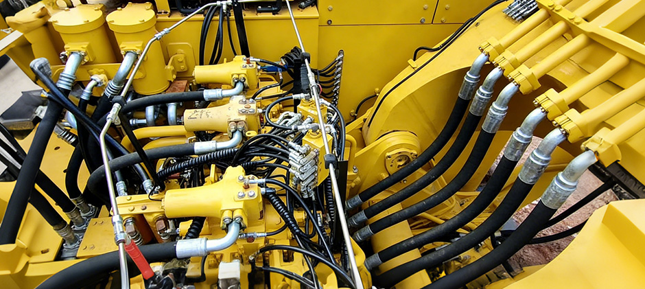
When your excavator boom is sluggish, your bulldozer blade seems weak, or your loader’s movements become jerky, the problem often lies within the machine’s hydraulic system. We will explain the three main types of hydraulic control valve diagram and their working principles, and common issues and troubleshooting to help you maintain the system more efficiently.
What Is a Hydraulic Control Valve?
Simply, hydraulic control valves are used to control where hydraulic oil goes, how much pressure it has, and how quickly it flows.
You can think of them as the “traffic controller” in the hydraulic system. The boom, bucket, tracks and other movements of the equipment are actually controlled by hydraulic oil directed by these valves. Although there are many types of valves, they can generally be divided into three categories:
- Directional control valve: determines where the oil flow (action direction)
- Pressure control valve: controls the pressure (force)
- Flow control valve: controls the flow rate (fast and slow action)
Knowing these three valve types captures the core of the hydraulic system. When you encounter problems such as sluggish equipment, slow movement, and jerky movement, it will be easier to know what went wrong.
Directional Control Valves
A directional control valve is like the “traffic controller” of a hydraulic system. On excavators and backhoes, when you move the control lever, these valves are what actually respond. They control when hydraulic oil flows and where it goes, allowing cylinders to extend or retract and motors to rotate, so the machine can perform different actions.
These valves are usually grouped together in a valve block, receiving signals from the operator in the cab. Almost every function—whether it’s lifting a load on a forklift or rotating the upper structure of an excavator—depends on them.
Directional control valves are mainly defined by two things:
- the number of ports (how many connections they have)
- the number of positions (how many operating states they can switch between).
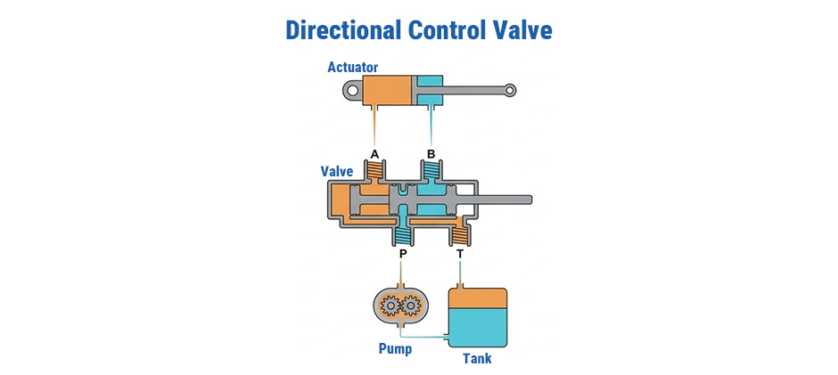
In heavy equipment, the most common type is the 4-way, 3-position valve. It has four ports—P (pump), T (tank), and A and B (to the actuator). The spool inside can move between three positions, each creating a different flow path.
How Does a Directional Control Valve Work
Let’s look at a typical diagram to understand how it works. It shows a 4-way 3-position spool valve connected to a double-acting cylinder. The cylinder is the actuator. The most important part of the valve is the spool. It is a metal rod that slides left and right inside the valve body. The spool has lands and grooves. It opens and closes different oil passages by moving. This changes the direction of oil flow.
Neutral Position (no operation)
When you do not operate the lever, the spool stays in the middle by spring force. At this time, the pump port (P) connects directly to the tank port (T). Hydraulic oil circulates at low pressure. It saves energy and reduces heat.
At the same time, the two working ports A and B are blocked. The cylinder or motor is locked. The actuator, such as the excavator boom, stays in place and will not drop.
Position 1 (Extend)
When you push the lever, the spool moves to one side. It moves right in the diagram. It opens new internal oil passages. High-pressure oil from the pump flows from P to A. It enters the cylinder and pushes the piston out. The piston rod extends. At the same time, port B opens. Used oil from the other side of the cylinder flows back to the tank through B.
Position 2 (Retract)
When you pull the lever, the spool moves to the opposite side. It moves left. The oil flow is fully reversed. High-pressure oil flows from P to B. It pushes the piston back. The piston rod retracts. Used oil from the other side of the cylinder flows back to the tank through A.
“A directional control valve does not produce power. It only directs where the power goes.” This simple and clever mechanical device lets you control the machine with precision.
Pressure Control Valves
If directional control valves decide where oil flows, pressure control valves control how strong the force is. Without them, the high pressure from the hydraulic pump can easily damage hoses and fittings. It can even break expensive parts like cylinders and motors.
The main job of pressure control valves is to act as relief valves. They provide safe pressure release. They are usually installed near the hydraulic pump. This group also includes reducing valves, sequence valves, and counterbalance valves. Each controls pressure at different points in the system.
For example, on a bulldozer, the relief valve stops the lift cylinder from breaking due to high pressure. When a loader bucket hits a hard object, the relief valve protects the whole hydraulic system.
How Does a Pressure Control Valve Work
The most common pressure control valve is the pressure relief valve. It’s simple but works really well: it balances the spring against the hydraulic pressure. Here’s how a basic, direct-acting relief valve works:
- Adjustment Screw: lets you set the max system pressure by changing spring tension (called the “cracking pressure”).
- Spring: keeps the valve closed under normal pressure.
- Piston (or Poppet): moves up to let fluid out when pressure gets too high.
- Source Pressure (Flow In): the main pressure coming from the pump.
- Flow Out: the path for extra fluid to go back to the tank.
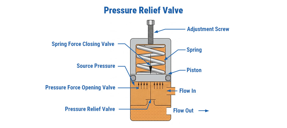
Works Step by Step:
- Normal operation: As long as pump pressure is lower than the spring force, the valve stays closed. All fluid goes to do work.
- Pressure spike: Say your excavator bucket hits solid rock. The cylinder can’t move, but the pump is still pushing fluid. Pressure rises fast.
- Valve opens: When pressure gets higher than the spring can hold, the piston lifts and lets extra fluid flow out to the tank.
- Pressure drops: Once the pressure goes back down, the spring pushes the piston down and closes the valve.
It all happens instantly, keeping the hydraulic system safe from damage.
Flow Control Valves
Pressure determines force, and flow determines speed. A flow control valve is the key part that controls how fast your machine moves. Whether you need to lower heavy, precise loads slowly and carefully, or dump a bucket of rocks quickly, you need flow control.
These valves work by controlling how much oil flows through the pipes over time. By limiting the oil going into the hydraulic cylinder, you slow down the extend and retract speed of the rod. Most modern off-highway machines already have flow control built into the main control valve. But for jobs that need extremely precise speed control, separate flow control valves are still widely used.
How Does a Flow Control Valve Work
The easiest way to control flow is to add a restriction, like putting your thumb over a garden hose. But a simple restriction has a big problem: when pressure changes, flow changes too. To fix this, most hydraulic systems use a pressure-compensated flow control valve. This smarter design keeps speed steady, no matter how the load changes.
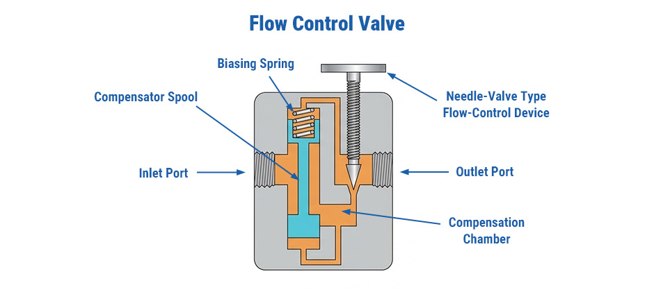
Let’s Break Down Its Parts:
- Needle-valve flow control: This is the adjustable opening. Turn the knob to move the needle in or out, making the opening bigger or smaller. This sets your speed.
- Compensator spool & spring: This is the “smart” part. The spool moves back and forth automatically to adjust the flow when pressure changes, keeping speed constant.
This Is How It Keeps the Speed Steady:
- First, the operator sets the desired speed by adjusting the needle valve (basically setting the flow).
- Oil flows in through the inlet and passes through the small opening made by the needle valve.
- At the same time, the compensator spool is constantly “watching” the pressure before and after the needle valve. Its job is to keep that pressure difference steady.
- If the load increases, like when lifting a heavier rock, the outlet pressure goes up. Normally, this would reduce the flow and slow things down. But the compensator spool reacts right away and opens a bit more, letting more oil through so the speed stays the same.
- If the load decreases, it does the opposite. It closes slightly to reduce the flow, preventing the movement from suddenly speeding up.
This smart design keeps the machine running smooth and steady, which is important for both getting the job done and staying safe on site.
Troubleshooting Common Hydraulic Control Valve Issues
When a machine starts to have problems, these are common if it’s valve related:
Jerky or Uneven Movement
For example, the cylinder or motor may speed up and slow down instead of moving smoothly. Generally, a problem in the flow control valve or contamination in the system causes the issue. Debris can partially block a small orifice, the compensator spool can stick, or air can enter the lines.
You can replace the filter first, check the valve for dirt, and then bleed the system.
Slowing Down and Low Power
For example, things that were easy to lift before now feel much heavier, and the machine may run hotter than usual. These issues usually come from pressure problems. An incorrectly set relief valve, internal leakage in the valve, or a blocked pipeline can cause them.
You can check and adjust the relief valve setting. If the valve is worn, it will send oil straight back to the tank instead of doing useful work.
External Oil Leakage
If you see oil dripping from the outside of the valve body, there is definitely a problem. In most cases, the seal (O-ring) is worn or damaged, or the valve body may be cracked due to impact.
The leak point needs to be found, the seal replaced, and the fittings tightened. If the valve body is cracked, it must be replaced.
No Response During Operation
You moved the lever, but the machine didn’t respond. If it is an electrically controlled valve, the solenoid may be faulty or there may be a wiring issue. If it is a mechanical problem, the spool may be stuck.
The electrical signal can be checked first. If the signal is normal, the solenoid may need to be replaced. If the spool is stuck, it usually needs to be disassembled and cleaned. In serious cases, the solenoid valve should be replaced directly.
Keep Your Machinery Running with the Right Parts
If you find that the valve is worn or damaged, replacing it is usually the easiest and most reliable fix.
Many aftermarket options work just as well and cost less. At FridayParts.com, you won’t have to overspend on repair parts. We offer quality hydraulic parts at competitive prices, so you get good value for your money.